
 Türkçe tr
 English en
 Русский ru
 العربية ar
 Español es
 Português pt
 Azərbaycanca az
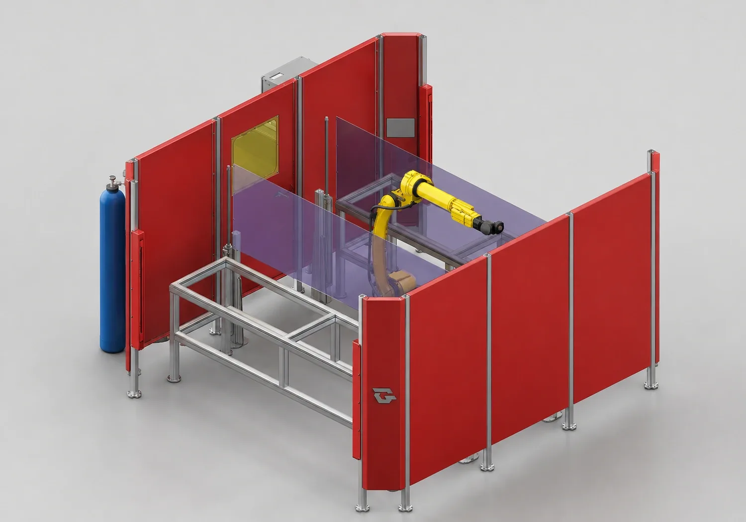
System 02 · Single-robot
Partitioned welding cell
A welding cell layout in which the work sections around the robot are separated by panels.
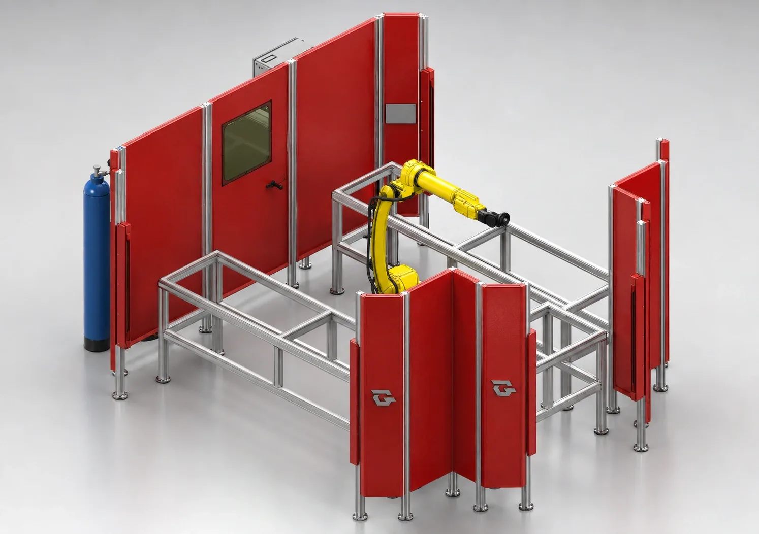
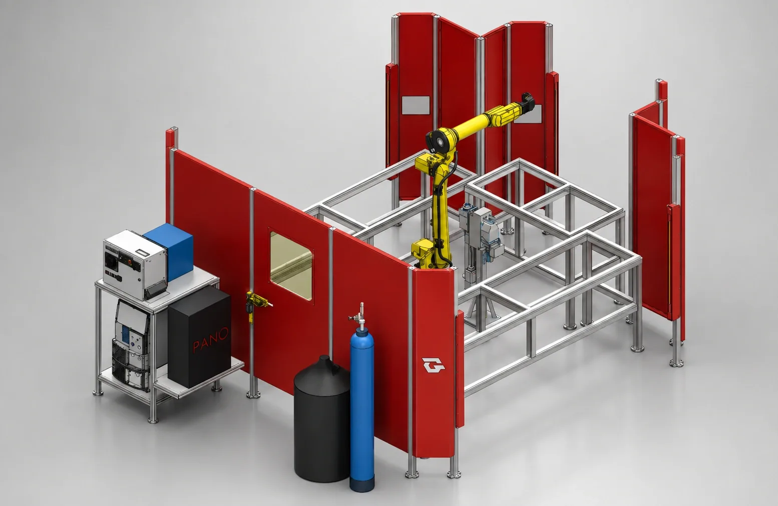
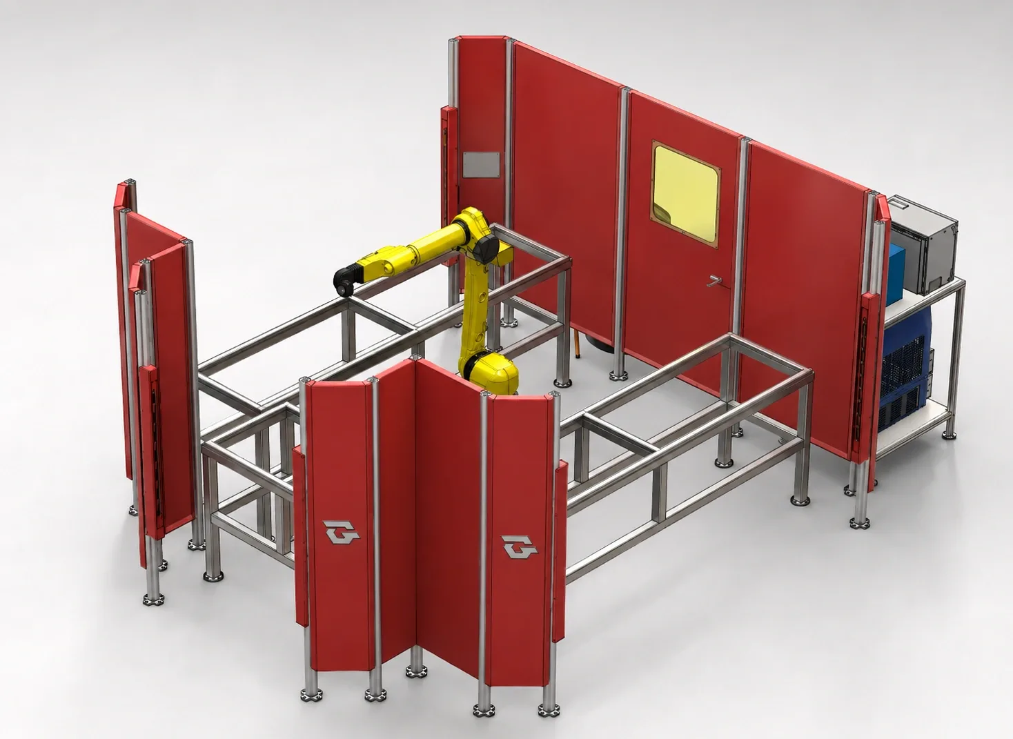
The images are intended to present the layout. Final equipment, dimensions and guarding are defined according to your application.
The 3D view could not be loaded. Check your connection and browser 3D support.
Drag to rotate; zoom with the wheel or with two fingers. The model shows the layout; dimensions, load capacity and cycle time are clarified for each project.
System 01
A welding cell layout with one robot in the centre and part loading areas on both sides.
Simply mention the system in the quote form; we will refine the layout for your part together.
The work areas placed on both sides of the robot create a layout in which part preparation and welding access can be assessed together. The fixtures on the frames are defined according to the part to be produced.
The component list describes the layout images. The final scope is defined in the quotation and application engineering.
How the part is loaded into each area, robot reach and operator access are assessed together. The operating sequence of the stations and the guarding layout are defined during project engineering.
Dimensions, load capacity, cycle time and safety scope cannot be verified from these images; they are clarified through an assessment specific to your project.
Let us discuss System 01Compare layout alternatives and choose the right starting point for your part.
A welding cell layout in which the work sections around the robot are separated by panels.
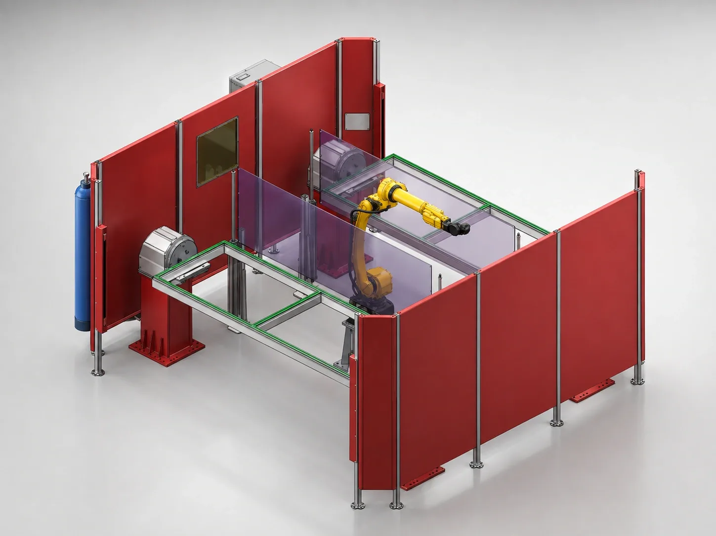
A welding station with a part carrier and positioning arrangement in front of the robot.
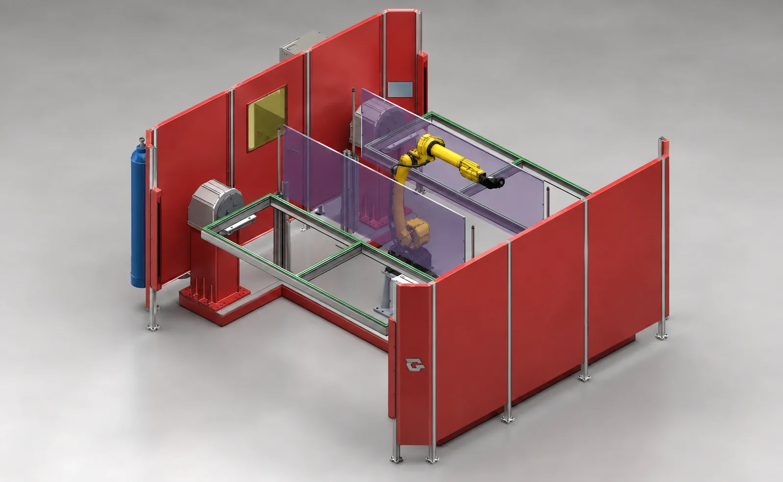
A single-robot welding station built around an extended part carrier frame.